Nurse Call Systems — the call chain from pull cord to the carer who answers
A nurse call system is judged by one thing: whether the right carer reaches the right room, in time, with a record of what happened. The system documented here is IP and SIP based and is assembled from four parts — call points, corridor indication, a nurse console and portable handsets — with no proprietary bus and no separate server room. This page follows a call from the pull cord to the answer, and gives the counting rules for a ward, a clinic and a nursing home. NEXVIA designs, manufactures, supplies and commissions the system; the terminals are manufactured by NEXVIA.
Bed-side and door-side stations, bathroom pull cords and wireless buttons on one IP and SIP system
Four call types separated at the call point: nurse call, bathroom emergency, staff assist and code blue
A corridor light over each room door — the unit tender documents usually call a dome light — in red, green, blue and yellow
Calls transfer automatically to a portable handset when the nurse station is unattended
Up to 10 wireless buttons on one bed-side station, linked over 433 MHz across 6–25 m indoors
Call and attendance logs can be viewed and exported from the console; zoned paging runs on the same system
A nurse call system for a ward is counted per bed and per call position, not per patient: one bed-side station per bed, one bathroom pull cord per bed or bathroom, a door-side station where code blue at the door is required, and one console per nurse station. The two reference plans printed in the care material count exactly that way — a 70-bed nursing home as 70 bed-side stations, 70 bathroom call points, 1 console and 15–20 portable handsets; a 50-bed clinic as 50 bed-side, 15 door-side, 15 bathroom points, 15 corridor lights and 1 console.
The chain has four links and every one of them is a network terminal: the call point raises the call, the corridor light over the door and the corridor display identify the room, the console answers with priority and colour coding, and a portable handset catches the call when nobody is at the station. The console supports up to 20 SIP lines, up to 116 DSS keys and up to 100 connected devices, and emergency calls require a password before the connection is made, so a person answers.
The physical rules decide whether it works on the day: bathroom pull cords put a 2 m cord at floor level, the wireless option is IP65 with its own battery and a 433 MHz link across 6–25 m indoors, and one bed-side station hosts up to 10 wireless buttons. Prices are not published here — NEXVIA quotes per ward count, room mix and the cable already in the building.
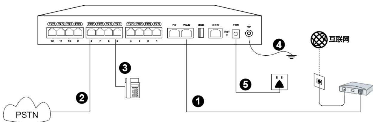
System wiring: internet uplink, PSTN lines, analog phones and grounding all land on one chassis
What goes wrong on this type of site
Ringing is not answering
A call that only rings the station fails as soon as the ward is busy. The chain widens instead: speakers can amplify the incoming call, the corridor display and the light over the door identify the room, and the call forwards to the W611W portable handset when the station is unattended.
The type of call changes the response
Nurse call, bathroom emergency, staff assist and code blue are different events with different urgency. The system separates them at the call point, shows them with colour and flash patterns, and prioritises them on the console with colour coding.
Count the call points before pricing the cable
Every bed, every bathroom and every door position is a device, and bathroom points are radio or wired depending on the building. The two reference plans count them explicitly — 50 bed-side and 15 door-side in the clinic, 70 bed-side in the nursing home — so they can be used as the template for a new ward.
Evidence after the event
Care providers need a record of who called and who attended. The console keeps call and attendance logs that can be viewed and exported, and the PBX can record calls in G.711 and G.729 where a recording server is part of the design.
Choosing by size
Size band
System
Devices
Notes
Care home — up to about 40 rooms
OM50G — 62 SIP trunks
One bed-side station per bed, one bathroom call point per bed, 1 × A320i console, 15–20 portable handsets
Scale the 70-bed ratios down to the room count. Ring groups hold up to 40 extensions on this model; capacity is published in SIP trunks because the maximum extension count is not stated.
OM1000-UC — 1000 SIP trunks, up to 200 concurrent calls per trunk
50 × Y501W-Y bed side, 15 × Y501W door side, 15 × KT30/KT31, 15 × CL-01,1 × A320i, 15–20 portables, 2 × CMD-01 per floor optional
Counts are the clinic plan printed in the care material; the corridor display and light quantities are marked optional there. The plan does not name a PBX model, so the model is a reference choice.
70-bed nursing home — 10 single and 30 double rooms
Counts as printed in the nursing-home plan: one bed-side station per bed and one bathroom call point per bed. Confirm the final bed and room counts, and the optional corridor items, on the quotation.
Hospital — several wards or buildings
OM1000-UC — 1000 SIP trunks
The per-ward counts repeated, one console per nurse station, 2–4 corridor displays per floor
SIP only, with dual hot standby and multi-site networking between buildings; the care material does not state a maximum number of stations per system.
Extension wing or refurbished floor
OM200G — 496 SIP trunks
New IP stations on the network, with existing analog call wiring terminated or bridged where pairs still reach the frame
Up to 96 analog ports on 24-line interface cards suits a wing that keeps part of its old wiring; PN1 converters cover rooms with two-core cable only.
Hosts up to 10 KT10/KT20/KT30 wireless buttons; powers and controls the CL-01 corridor light; handset on the -Y variants; PoE support per the product guide
Y501W
Door side
Staff emergency call and code blue at the door
Same station platform; the 50-bed clinic plan uses 15 door-side stations
KT30
Bathroom
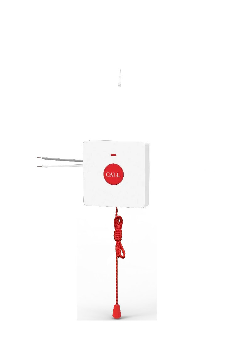
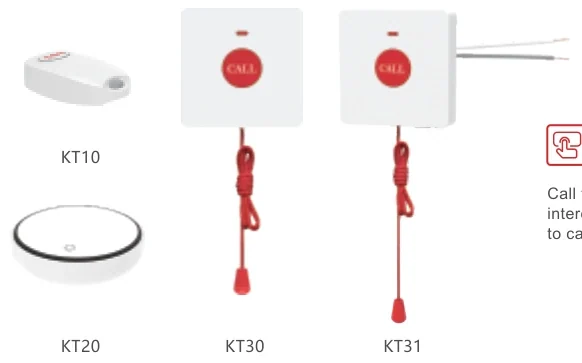
Wireless bathroom emergency pull cord
IP65, battery inside, 2 m cord, 433 MHz link over 6–25 m indoors
KT31
Bathroom
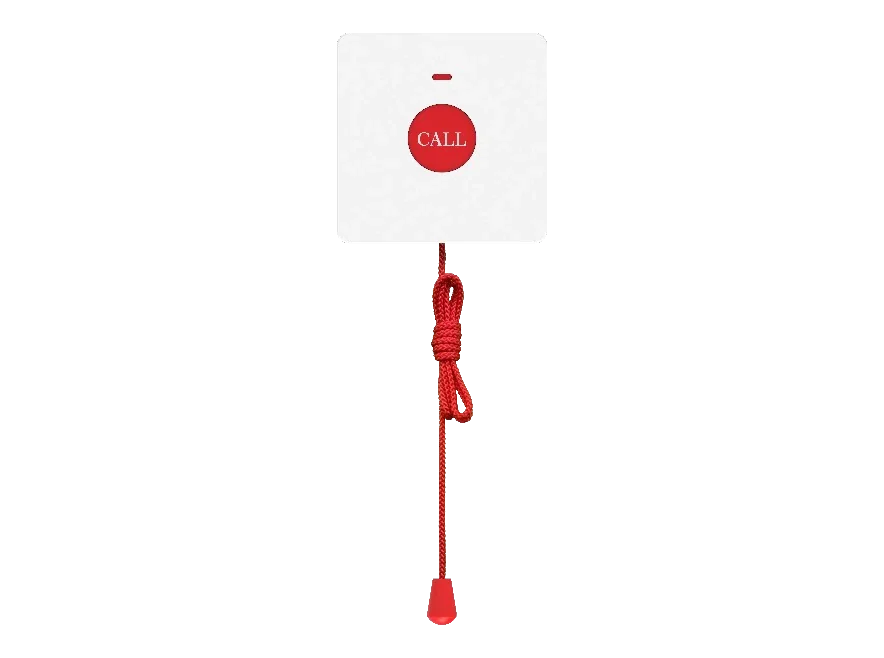
Wired bathroom emergency pull cord
IP44, no power needed, 2 m cord, wired to the Y501 series station
KT10 / KT20
Pendant or wall
Wireless push button or emergency button
Self-powered (no battery); 433 MHz to the Y501 series station or X305 phone; up to 10 per station
CL-01
Over the room door
Corridor status light (the dome-light position in tender documents)
Red, green, blue and yellow states; 86 box or wall mounting; powered and controlled by the Y501 series station
CMD-01
Corridor, public area
Shows room and call status to staff passing by
Up to 30 prioritised messages; double-sided LED display, 128×32 dots; multilingual; works with the nurse console
10.1-inch 1280×800 touchscreen, 20 SIP lines, up to 116 DSS keys, up to 100 devices, 92 dB speaker, Android 9.0
W611W / W620W
Carer on the move
Receives calls forwarded from an unattended station
Wi-Fi 6 dual-band; W611W IP67, 1900 mAh, up to 9 h / 200 h; W620W 3000 mAh, up to 13 h / 240 h
FH-S01 / A212
Ward or corridor audio
Amplifies the incoming call so staff elsewhere hear it
PoE supplied, up to 20 multicast zones; A212 published as PoE 8 W / PoE+ 15 W with talkback
This design against a conventional bus nurse call system
Requirement
Conventional bus system
This IP design
What changes operationally
Cabling
Dedicated bus cable to every call point
SIP terminals on the site network; the bed-side station drives the corridor light
The ward shares the data network instead of a separate cable installation
Bathroom call point
Wired back to the bus, or a radio receiver box on the corridor
KT30 wireless with its own battery across 6–25 m, or KT31 wired to the station
Wet walls and heritage finishes do not force a new cable
Adding a room or moving a bed
Re-address the bus and re-label the field
Create a SIP extension and pair the buttons; terminals used with the console are scanned and provisioned automatically
Layout changes are configuration work
Corridor indication
Lamp field above the door and a corridor lamp panel
CL-01 light per door plus CMD-01 display with up to 30 prioritised messages
The room number and call type are readable in the corridor, not only at the desk
Staff away from the station
No portable, or a separate pager contract
Automatic transfer to the W611W portable handset, plus speaker amplification
The call follows the carer
Records
Paper log or a proprietary logger
Call and attendance logs exported from the console; G.711/G.729 call recording where a recording server is used
A reviewable record after an incident
Site telephony
A second telephone system, separately wired
The same PBX carries care calls and site telephony on 24 to 1000 SIP trunks
One dial plan and one maintenance routine
Deployment by area
Area
Device
Note
Bed side
Y501W / Y501W-Y bedside station
Nurse call, staff assist call and staff presence, with a handset on the -Y variants. Hosts up to 10 KT10/KT20/KT30 wireless buttons and powers and controls the CL-01 corridor light.
Door side
Y501W door-side station
Staff emergency call and code blue at the door; the 50-bed clinic plan uses 15 of them.
Bathroom
KT30 wireless or KT31 wired pull cord
A 2 m pull cord for the bathroom emergency call. KT30 is IP65 with a battery inside and a 433 MHz link over 6–25 m; KT31 is IP44, needs no power and is wired to the Y501 series station.
Corridor, over the door
CL-01 corridor light
The dome-light position in a tender: 86 box or wall mounted, red, green, blue and yellow states, powered and controlled by the station in that room.
Corridor, public area
CMD-01 corridor display
Room and call information with up to 30 prioritised messages on a double-sided 128×32 dot display, multilingual, working with the nurse console.
Nurse station
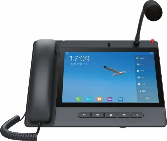
A320i console (A308i for a secondary position)
10.1-inch 1280×800 touchscreen, 20 SIP lines, up to 116 DSS keys, up to 100 connected devices, 92 dB speaker. Password-gated emergency calls, colour-coded priority, logs, broadcasting and access control.
Carer on the move
W611W / W620W portable handset
Receives forwarded calls. W611W is IP67 with 1900 mAh (up to 9 h talk / 200 h standby); W620W has 3000 mAh (up to 13 h / 240 h) with dual microphones and H.264 video preview.
Questions buyers ask
What does a nurse call system include?
Four parts, and all four have to be in the design: the call points (bed side, door side, bathroom and wireless buttons), the annunciation (a light over each door and a corridor display), the answering station (the console at the nurse station), and the portables that carry the call to a carer who is not at the station.
Bed-side station: nurse call, staff assist call and staff presence on the Y501 series.
Bathroom: a 2 m pull cord, wireless KT30 or wired KT31.
Console: A320i with 20 SIP lines, up to 116 DSS keys and up to 100 connected devices.
Portables: 15–20 per site in both reference plans, so a call can be answered away from the station.
Does a nurse call system need its own cabling?
No. The call points are network terminals: the Y501 series station has PoE support per the product guide, and it powers and controls the corridor light over the door, so one network run serves the station and its indication rather than a second cable for the lamp.
The wireless bathroom button needs no cable at all: KT30 carries its own battery and links over 433 MHz across 6–25 m indoors.
The wired alternative, KT31, needs no power of its own — it is a two-wire connection back to the station in the room.
Where the building has two-core cable only, the PN1 converter carries network and power over the existing pair, up to 1600 m for the network function without power.
One 86 box is enough for the in-room panel and for the CL-01 light position, which is why the corridor indication is a fitting, not an installation.
What is the nurse call dome light, and where does it go?
The dome light is the light over the room door that shows a call without anyone reading a screen. In this range it is the CL-01 corridor light, mounted above the door in an 86 box or on the wall, powered and controlled by the bed-side station in that room.
It shows red, green, blue and yellow to indicate different statuses, so a carer in the corridor can see which room is calling and what kind of call it is.
It is counted per room — 15 in the 50-bed clinic plan, 40 in the nursing home plan as an option.
Because it is driven by the station, it also acts as a fault indicator: if the station is unpowered, the corridor indication fails with it, which is why the station's PoE supply is the point to check first.
How many call points does each room need?
Three for a full care room and two as a minimum. The published count is one bed-side station per bed, one bathroom call point per bed or per bathroom, and a door-side station where code blue at the door is required. A 4-bed room therefore carries four bed-side stations before any corridor items.
The 50-bed clinic is laid out as 10 four-bed and 5 two-bed rooms, and the plan counts 50 bed-side against it — one per bed.
Bathroom points are counted per bed in both plans (15 and 70), because not every room has the same sanitary layout.
Wireless buttons are the flexible part: up to 10 KT10/KT20/KT30 buttons can sit on one bed-side station, covering positions a fixed point cannot reach.
Round up for day rooms, treatment rooms and staff rooms, then confirm the site count on the quotation.
What happens when the nurse station is empty?
The call moves rather than waiting. It transfers automatically to the W611W portable handset when the station is unattended, and ward speakers can amplify the incoming call so staff elsewhere in the ward hear it.
Both reference plans issue 15–20 portable handsets per site so there is always a handset on shift.
The corridor display keeps showing the room and call status while the call is unanswered.
The console logs the call and its attendance, so an unanswered call is visible in the record rather than lost.
Can a nurse call bell system be added to an existing phone system?
Yes, if the existing system is SIP based: the stations and console register as SIP terminals like any other extension, and the console takes 20 SIP lines. The care system is documented as IP and SIP based with no proprietary server requirement.
The PBX supplies the dial plan and trunks; ward traffic and site telephony share it, from 24 SIP trunks on the OM20G to 1000 on the OM1000-UC.
Integration with access control and PA systems is stated in the care material, so door phones and paging can be added later without a second platform.
Where the existing PBX is not SIP capable, the system can be delivered with its own PBX — the terminals do not change, only the routing core does.
Which wireless technology do the buttons use, and how far do they reach?
The wireless buttons use a 433 MHz link with a published working range of 6–25 m indoors, and up to 10 buttons can be paired to one bed-side station. KT10 and KT20 are self-powered (no battery) and KT30 carries its own battery.
The 6–25 m figure is a design input, not a guarantee: check the distance from the station to each button, and count walls rather than metres on a straight line.
Where the distance is too long, the wired KT31 removes the radio link entirely for a small cable run.
Buttons are battery-free or battery-fed by design so a flat battery in a pendant does not silently disable the call point.
Can the system be integrated with access control and public address?
Integration with access control and PA systems is one of the headline points of the care material, and the same range includes door phones with remote unlocking and SIP speakers for zone broadcasting. Bring those interfaces into the enquiry so the wiring and the extensions are designed together.
Zoned paging and one-click emergency broadcast are part of the same system, and the speaker family supports up to 20 multicast zones with prioritisation.
Door unlocking during an intercom call and push notifications are documented for the console and door-phone combination.
Advanced feature sets such as HIS/EHR/RTLS integration and multi-nurse-station interlink are outside what this system documents — raise them at enquiry stage if the tender requires them.
Cabling, power and network notes
The Y501 series station is the powered node in the room: PoE support per the product guide, and the station hosts the room buttons and the corridor light.
KT31 needs no power of its own and is wired back to the Y501 series station with a two-wire connection; KT30 and the KT10/KT20 buttons are radio devices on a 433 MHz link, so no data cable is run to them.
The 433 MHz working range is 6–25 m indoors — check it against the distance between the host station and each radio button before fixing positions, and count the walls between them.
CL-01 is powered and controlled by the Y501 series station rather than taking its own PoE run; a supplementary guide also allows an independent 12 V DC adapter where a separate supply is preferred.
Speakers are PoE (FH-S01 to IEEE 802.3af; A212 published as PoE 8 W / PoE+ 15 W) and mount in the ward or corridor where the call must be heard.
The console needs a network drop with PoE, and on a multi-ward site the plan must say which console owns which ward before commissioning.
Keep the call-point wiring and the data cabling on the same as-built drawing: the corridor light, the station and the console are one circuit electrically even though they are three devices.
Reading the alert
Alert indication as stated in the care material
Signal
How the system shows it
Nurse call
Slow flash on the station
Bathroom emergency call
Quick flash
Staff assist call
Slow flash
Code blue
Quick flash
Staff presence
Indicated on the station
Corridor light (CL-01)
Red, green, blue and yellow to indicate different statuses
Corridor display (CMD-01)
Room and call information, with up to 30 prioritised messages
Ward speaker (FH-S01 / A212)
Amplifies the incoming call when the station is unattended
Multiple alert methods are used together: incoming calls can be broadcast through speakers, colour and flash pattern indicate the call type, and the corridor display shows the call information. The design decision is which of them is primary in which ward.
Deploying it floor by floor
One bed-side station per bed, one bathroom call point per bed or bathroom, and door-side stations where the ward layout calls for code blue at the door.
Corridor displays are placed per floor: the plans list 2 per floor for the clinic and 4 per floor for the nursing home, both optional.
The corridor light goes over each room door and is powered by the station in that room, one per room.
Portable handsets are issued by shift — 15–20 per site in both reference plans — so a call can be answered away from the station.
Console configuration and extension setup can be handled centrally, and terminals used with the console are scanned and provisioned automatically.
Commission ward by ward and test the escalation order, not just the call: raise each call type from each device and watch where it lands.
Where nurse call meets the rest of the building
The system is IP and SIP based and integrates with access control and PA systems, with zoned paging and one-click emergency broadcast.
Broadcasting and door phones can be combined with the care system, supporting emergency announcements, zone broadcasting, one-click calls and remote door unlocking.
Call and attendance logs support record tracing after an incident.
The material positions the system for nursing homes and small to mid-sized hospitals, including sites upgrading from an analog or bus system.
Advanced feature sets such as HIS/EHR/RTLS integration and multi-nurse-station interlink are outside what this system documents — a tender requiring them needs a different system conversation at enquiry stage.
A counting method you can take to a survey
The two published plans are useful less as equipment lists than as a ratio. Read them as: one bed-side station per bed, one bathroom call point per bed, one door-side station per room where code blue at the door is needed, one console per nurse station, and 15–20 portables per site regardless of size.
Start with the bed count, because every plan figure follows from it: 50 beds produced 50 bed-side and 15 bathroom points in the clinic, and 70 beds produced 70 and 70 in the nursing home.
Then count rooms for the door-side stations and the corridor lights: 15 door-side and 15 lights against the clinic's 15 rooms.
Then add the corridor displays by floor (2 or 4 per floor in the plans) and the portables by shift (15–20 per site).
Finally check the two physical limits on site: the 6–25 m radio range from each station to its wireless buttons, and the 100-device console limit on a large floor.
Ratios are a starting point for a survey, not a substitute for one. The final count is confirmed on the quotation.
Compliance, standards and local requirements
Emergency-call priority has to be designed, not assumed
The published behaviour is that emergency calls require a password before the connection is made, so the call is answered by a person rather than auto-connected. Around that, the design has to say what happens in the first seconds: which device rings first, how long it rings before escalation, which portable catches it, and which speaker amplifies it. None of those settings is regulation — they are local procedure, and they should be written into the handover document and tested ward by ward.
Wiring, PoE and the corridor indication circuit
The bed-side station is the powered node: PoE support per the product guide, and it powers and controls the CL-01 corridor light. Wireless buttons are self-powered or battery-fed, and the wired pull cord needs no power of its own. PoE classes, cable classes, mounting heights for pull cords and the 86 box standard are local installation matters — confirm them against the applicable wiring code before first fix.
Accessibility is a physical requirement
A call point that cannot be reached is not a call point. The bathroom options both place a 2 m pull cord at floor level so a person who has fallen can still reach it; KT31 is IP44 and KT30 is IP65, which decides where each can be installed. Button and station positions, the height of the corridor display and the readability of the light over the door should be checked on site with care staff rather than taken from a drawing.
No certification is claimed — confirm against local code
The published comparison for this care system records no third-party safety certification for the system, and this page makes no certification claim. National rules on call-system performance, alarm interfaces to a fire panel, and the retention of care records differ by country and by facility type. A compliant design is one that has been checked against the local code and the facility's own care policy by the buyer's compliance officer — use this page as the technical input to that review, not as its conclusion.
Can the bathroom call point be reached from the floor?
Yes. Both bathroom options carry a 2 m pull cord: KT30 is wireless and IP65 with a battery inside, and KT31 is IP44, needs no power of its own and is wired to the Y501 series station.
How does the system show which room is calling?
The CMD-01 corridor display shows the room and call status, the CL-01 light over the door shows the state in red, green, blue and yellow, and the console shows the prioritised, colour-coded call.
Can we see who attended and when?
Call and attendance logs can be viewed and exported from the console, which is what the care material means by record tracing. Call recording in G.711 and G.729 is available where a recording server is part of the design.
How many wireless buttons can one room have?
Up to 10 KT10/KT20/KT30 buttons can be hosted by one Y501 series station, and the same buttons work with the X305 big-button phone. That is what covers a pendant, a wall position and a bathroom in one room without extra cabling.
Is there a certificate for the care system?
No certification is claimed here. The published comparison for this care system records no third-party safety certification, and this page does not assert any. Tenders that require a specific listing must confirm it against local code and raise the requirement at enquiry stage.
Does the console replace the ward telephone?
It can. The A320i is a console IP phone with 20 SIP lines and up to 116 DSS keys, so ward calls, internal calls and outside calls can be handled at the same position on the same PBX that carries the rest of the site.
What is needed in the room before installation?
A network run with PoE to the bed-side station position, an 86 box for the in-room panel, and a mounting position above the door for the corridor light. The bathroom point needs either a two-wire run back to the station (KT31) or nothing at all (KT30). Confirm the mounting heights with care staff during the survey.
Project evidence
We have not published a named reference project on this page. The site does not carry customer names or installation records until the client confirms in writing which projects may be made public.
Six facts build a configuration: site type, extensions or rooms, simultaneous calls, areas to cover, existing lines and the documents you already hold. Send as many as you know — nothing has to be final before the first reply.
Analytics cookies.We use Google Analytics and Microsoft Clarity to understand which pages are used. They load only if you accept. You can reject and still use the whole site.Cookie Policy