
The pair is doing two jobs at once
A 2-wire run carries signal and power together, so distance, device count and pair condition all interact. The published figures give the envelope; the survey gives the answer per position.
IP Telephony & SIP Communication Systems · Guangzhou, China
Scenarios · retrofit cabling
A 2-wire IP phone is not a phone with a smaller connector: it is a phone or device that receives both its network connection and its power over two copper cores, which is the cable a hotel, a hospital or a period building already has inside it. The technique comes from the 2-wire product family in this catalogue — a converter for a single point and two 2-wire switches for a floor — and it is the documented answer to the refurbishment that cannot open the walls. This page sets out what the technique carries, what the published distance limits are, and how the 2-wire telephone models themselves fit into the plan. NEXVIA designs, manufactures, supplies and commissions the system; the converters, switches and handsets are manufactured by NEXVIA.
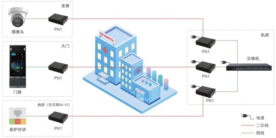
The 2-wire technique solves one problem: a building where the only cable that exists is a two-core pair. Instead of running data cable to every position, a converter or switch places the network signal and the power onto that pair. A single position is served by the PN1, which reaches up to 1600 m for the network function without power and is supplied locally at AC 100–240 V; a floor is served by the PN8 (up to 8 two-wire devices) or the PN24 (up to 24 devices), both rated to a maximum connection distance of 300 m for network plus power with a built-in AC 100–240 V supply.
Two things decide the design: distance and power. The distance figures are published per device rather than as a single rule — 1600 m for the network function without power on PN1, 300 m for network plus power on PN8 and PN24 — so the survey has to record both the run length and the number of devices at the far end. Power is the second: PN1 takes its supply locally, PN8 and PN24 have built-in supplies, and PN24 is a standard 1U chassis for a riser or equipment cabinet.
The handsets themselves are published models, not adaptors bolted to ordinary phones: the X303-2 Wire is a 2.4-inch colour-screen phone that takes power and network from the 2-wire supply, and the H1-2 Wire is a service handset with 8 programmable keys, G.722 and Opus audio and faceplate customisation. Prices are not published on this site — every retrofit is quoted per point count, device mix and the measured condition of the existing pairs.
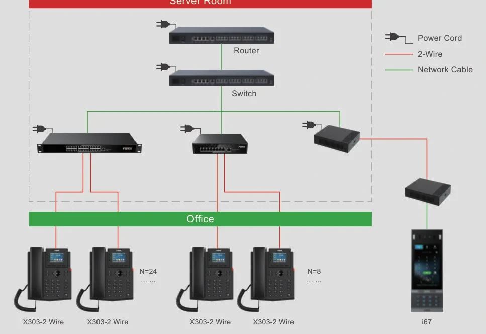
A 2-wire run carries signal and power together, so distance, device count and pair condition all interact. The published figures give the envelope; the survey gives the answer per position.
The 2-wire family publishes specific handsets — the X303-2 Wire and the H1-2 Wire — plus the door, care and speaker devices that use the same technique. Match the position to the published list rather than adapting a general-purpose phone.
PN1 needs an AC 100–240 V supply at the position, while PN8 and PN24 have their own supplies and PN24 is a 1U chassis. The electrical design has to reach the same points as the cabling design.
New cable where the walls are open, converters on the pairs that remain, analog devices on FXS ports during a phased changeover: a retrofit is rarely uniform, and the model should be planned on the finished requirement rather than the first phase.
| Size band | System | Devices | Notes |
|---|---|---|---|
| A single position on a pair — one room, one door, one handset | Any OM model, with a PN1 converter at the position | 1 two-wire device: a 2-wire IP phone (X303-2 Wire / H1-2 Wire), a door phone, an indoor unit or a care station | PN1 carries network and power over the existing two-core cable, up to 1600 m for the network function without power, with a local AC 100–240 V supply. The 1600 m figure applies to the network function without power, so a powered device needs a shorter run. |
| A floor or a riser section — up to 8 points | OM20G or OM50G — 24 or 62 SIP trunks | Up to 8 two-wire devices on a PN8, fed from the PBX switch through the existing riser | The PN8 cascades over Ethernet cable, has a built-in power supply at AC 100–240 V, and is rated to a maximum connection distance of 300 m for network plus power. |
| A large floor, wing or multi-floor riser — up to 24 points | OM50G or OM200G — 62 or 496 SIP trunks | Up to 24 two-wire devices on a PN24 in a standard 1U chassis, with PN1 converters for isolated points beyond it | PN24 has the same 300 m limit for network plus power and a built-in AC 100–240 V supply, and its 1U form factor suits a riser cabinet or a communal equipment room. |
| Hotel or apartment refurbishment on the existing riser | OM50G — 62 SIP trunks; up to 12 analog ports where pairs still reach the frame | Room handsets and door stations at the existing points, with PN converters per floor and per isolated position | The residential material labels this the historical-building retrofit case, described as needing no new wiring. Rooms that can take a data run should still take one; the 2-wire route is for the positions that cannot. |
| Mixed building — part new cable, part existing pair | OM200G — 496 SIP trunks; up to 96 analog ports on 24-line interface cards | New IP devices on data cabling where the walls are open, PN converters on the pairs that remain, analog extensions on FXS ports during a phased changeover | A mixed route per floor is the normal outcome of a refurbishment. Plan the model on the requirement at the end of the project rather than on the wiring of the first floor converted. |
| Greenfield installation where data cabling is planned anyway | OM20G to OM1000-UC — 24 to 1000 SIP trunks | Standard PoE IP phones on data cable, with the 2-wire devices used only where a pair is genuinely the only option | The 2-wire technique is a retrofit tool, and it is quoted per position. Where a new data run is possible, PoE on the published models is usually the simpler design. |
| Model | What it is | Published capability | Distance, power and notes |
|---|---|---|---|
| PN1 | 2-wire converter for a single point | Extends network and power over an existing two-core pair to the device at the far end | Up to 1600 m for the network function without power; external power AC 100–240 V; the image label in the solution brochure ties it to historical building retrofit |
| PN8 | 2-wire PoE switch for up to 8 devices | Network plus power over 2-wire, switchable; cascading via Ethernet cable; up to 8 two-wire devices | Maximum connection distance 300 m for network plus power; built-in power supply AC 100–240 V |
| PN24 | 2-wire PoE switch for up to 24 devices | Network plus power over 2-wire, switchable; up to 24 two-wire devices | Maximum connection distance 300 m for network plus power; built-in power AC 100–240 V; standard 1U chassis |
| X303-2 Wire | 2-wire IP phone | Colour-screen desk phone in the X300 series with 2-wire power and network supply | 2.4-inch colour screen; the material states the 2-wire supply rather than a PoE class, so the position power is confirmed with the converter or switch design |
| H1-2 Wire | 2-wire service handset, hotel and guest-room use | 8 programmable service keys with speed-dial functions, G.722 and Opus wideband audio, faceplate customisation | Supports 2-wire power and network supply; the entry handset of the H series in 2-wire form |
| PoE IP phones (for comparison) | The same roles on a data network | Integrated PoE is published on models such as the H2U, H3W, H4W, H5W and H6W, and on most V and X desk phones | One network run per position; the option wherever a data cable can be installed |
| Requirement | Pulling new network cable | This 2-wire design | What changes operationally |
|---|---|---|---|
| The riser | Open the riser, pull data cable to every floor and every room, make good the finishes | The existing pair carries network and power; PN8 or PN24 distributes a floor and PN1 covers isolated points | The building keeps its finishes, and the work is shorter |
| The position | One data outlet plus a PoE port on a switch | One converter or one 2-wire switch port, with the published distance limits applied | A position is a port on the converter rather than a switch port |
| Distance | The usual 100 m Ethernet limit to the outlet, and less with patch cords | PN1 reaches up to 1600 m for the network function without power; PN8 and PN24 reach 300 m for network plus power | Long risers and outbuildings become reachable without an intermediate switch |
| Power | The switch provides PoE up to its budget | PN1 takes a local AC 100–240 V supply; PN8 and PN24 have built-in supplies at AC 100–240 V | Power is provisioned at the converter or the floor switch rather than at the cabinet |
| The devices | Any PoE SIP terminal | 2-wire devices — the X303-2 Wire and H1-2 Wire handsets — and door phones, indoor units, care stations and speakers on the same pair | The phone model list is narrower, so the design is confirmed per position |
| Change of use later | A new outlet and a switch port | A port on the converter or a new converter at the position | Room changes stay cheap as long as a pair reaches the position |
| Risk to manage | Cable damage in the riser | Pair condition, distance and device count all matter, because the pair is carrying both signal and power | Measure and record every reused pair at survey, and keep the record with the as-built drawings |
| Area | Device | Note |
|---|---|---|
| A single position with only a pair available | PN1 2-wire converter | Carries network and power over an existing two-core cable, reaching up to 1600 m for the network function without power, with a local supply at AC 100–240 V. The solution material labels it for historical building retrofit. |
| A floor or wing with up to 8 points | PN8 2-wire PoE switch | Network plus power over 2-wire for up to 8 two-wire devices, cascading over Ethernet cable, with a built-in power supply at AC 100–240 V and a maximum connection distance of 300 m for network plus power. |
| A large floor or multi-floor riser with up to 24 points | PN24 2-wire PoE switch | Up to 24 two-wire devices on the same 300 m network-plus-power limit, with a built-in supply at AC 100–240 V in a standard 1U chassis for a riser or equipment cabinet. |
| Desk or back-office position on a pair | X303-2 Wire | Colour-screen desk phone with a 2.4-inch display that takes 2-wire power and network supply; the X300 series build in 2-wire form. |
| Guest room or service position on a pair | H1-2 Wire | 8 programmable service keys with speed-dial functions, G.722 and Opus wideband audio and faceplate customisation, with 2-wire power and network supply. |
| Door, room or ward position on a pair | Door phones, indoor units and care stations fed from the same pair | The same technique is used for entrance stations, indoor units and care stations, which is what makes a whole-building retrofit possible rather than a single telephone position. Confirm the device and its power at each point on the quotation. |
| Positions that can take a data run | PoE SIP phones and speakers on standard cable | Integrated PoE is published on the H2U, H3W, H4W, H5W and H6W hotel handsets and on most V and X desk phones, with the SIP speaker family on PoE as published — the simpler route wherever a network cable can be installed. |
It is a telephone that receives its network connection and its power over two copper cores, instead of over a standard four-pair network cable with PoE. The range includes the X303-2 Wire, a colour-screen desk phone with a 2.4-inch display, and the H1-2 Wire, a service handset with 8 programmable keys and G.722 and Opus audio.
It depends on the device, and the published figures are specific: PN1 reaches up to 1600 m for the network function without power, while PN8 and PN24 are rated to a maximum connection distance of 300 m for network plus power.
The PN8 carries up to 8 two-wire devices and the PN24 up to 24. Both have a built-in power supply at AC 100–240 V and the same 300 m limit for network plus power, and the PN8 can be cascaded over Ethernet cable while the PN24 is a standard 1U chassis.
More than telephones. The 2-wire family is documented as carrying network and power to the devices at the far end, and this catalogue uses the same technique for door phones, indoor units, care stations and speakers — which is what makes a whole retrofit possible rather than just a telephone position.
Sometimes you should, and the design says so: where a wall is open, a data run with a PoE device is the simpler and more flexible solution. The 2-wire route exists for the positions where opening the building is not possible — stone walls, heritage finishes, occupied hotel floors and long risers.
Four things per position: the pair count and condition, the run length, the device that has to sit at the far end, and whether power is available locally. Those four answers decide between a PN1, a PN8 or PN24 port, a new cable run and, in some cases, leaving the position on an analog FXS port.
Yes, wherever a pair reaches and a converter or switch port is available. That is the point of designing the distribution this way: a new position is a port on the floor switch or a new PN1 at the point, rather than a new riser cable.
The 2-wire route, point by point
| Element | Published figure or fact | What it decides |
|---|---|---|
| Cable | An existing two-core pair in the riser or the wall | Whether a position can be reached without new cabling at all |
| Signal and power | Carried together over the pair to the device at the far end | That the pair is doing two jobs, so distance and load both matter |
| PN1 single point | Up to 1600 m for the network function without power; external AC 100–240 V | Isolated positions, outbuildings and heritage rooms |
| PN8 distribution | Up to 8 two-wire devices; 300 m for network plus power; built-in AC 100–240 V; cascades over Ethernet cable | A wing or a small floor |
| PN24 distribution | Up to 24 two-wire devices; 300 m for network plus power; built-in AC 100–240 V; 1U chassis | A full floor or a larger wing, in a riser cabinet |
| Handsets | X303-2 Wire (2.4-inch colour screen) and H1-2 Wire (8 programmable service keys, G.722 and Opus) | The phone on the desk in a 2-wire design |
| Other devices | Door phones, indoor units, care stations and speakers on the same technique | The scope of a retrofit beyond telephony |
The 1600 m figure is published for the network function without power, and 300 m for network plus power — read the two together before choosing a route for a powered device.
A two-core pair that carries network and power is being used outside its original purpose, so the design case rests on measurement rather than assumption: pair count, continuity, insulation, run length and the number of devices at the far end. The published figures are PN1 at up to 1600 m for the network function without power, and PN8 and PN24 at a maximum connection distance of 300 m for network plus power. Local wiring rules on separation from mains, containment, earthing and the reuse of existing cabling apply, and they differ by country — confirm them with the site own contractor, and record every reused pair on the as-built drawing so the next alteration is not a guess.
The 2-wire parts of the system have their own supply requirements: PN1 takes a local AC 100–240 V supply at the position, while PN8 and PN24 have built-in supplies at AC 100–240 V and PN24 mounts in a standard 1U chassis. That means a riser cabinet or a nearby socket is part of the design, and the person specifying the installation should know which points need a supply and which do not. Whether a local supply is acceptable in a particular riser, and how it is protected, are local electrical matters to be confirmed with the site own electrical contractor.
Where a two-core route is used for a lift intercom, a care call point or an emergency call station, the communication chain may be subject to a code that says how it must remain available — including what happens when a normal supply fails. A converter in that chain is a dependency, and the design has to say so. The published material records no certification and this page makes no conformity claim; the arrangement for any emergency position must be confirmed with the lift, fire or care adviser and the local code authority before the equipment is ordered.
The honest limit of this technique is where a pair does not exist, is damaged, or is too long for the device count at the far end. In those cases the options are a new cable run, a wireless device where the model supports one — such as the Wi-Fi 6 hotel handsets or the 433 MHz care buttons — or leaving the position on an analog FXS port during a phased changeover. Writing that decision down per position, rather than promising that every position can be converted, is what keeps a retrofit project deliverable.
We have not published a named reference project on this page. The site does not carry customer names or installation records until the client confirms in writing which projects may be made public.
Page author: NEXVIA EngineeringPublished:Last updated:
Covers: 2 wire ip phone · two wire intercom · 2 wire intercom system · hotel retrofit wiring · ip phone over existing cabling
All IP telephony, intercom and paging equipment in this design is supplied and integrated by NEXVIA.
Running an existing platform
Replacing an older system
Explore Products
Carries network and power over existing two-core cable, for retrofit work.

Ten service keys and door-phone control for rooms that need a fixed contact list.
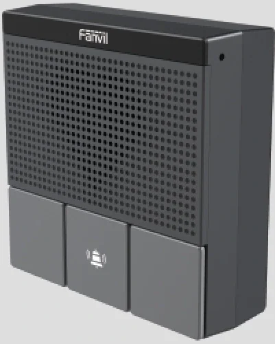
A wall panel for security calls, intercom and MP3 broadcast.
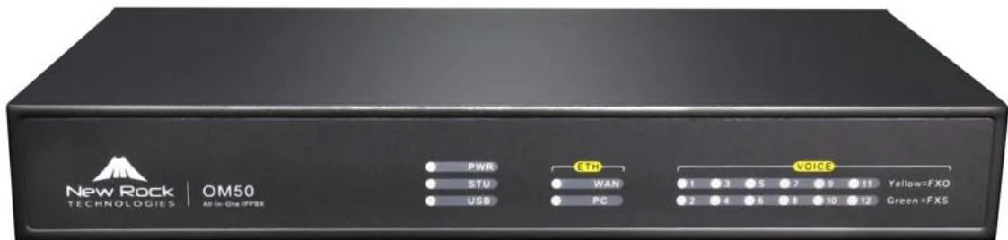
Three interface cards and 62 SIP trunks for offices that keep their analog lines.
Send us the site type, the number of extensions or rooms and the areas to cover — we will come back with a configuration and quotation.
Six facts build a configuration: site type, extensions or rooms, simultaneous calls, areas to cover, existing lines and the documents you already hold. Send as many as you know — nothing has to be final before the first reply.